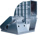


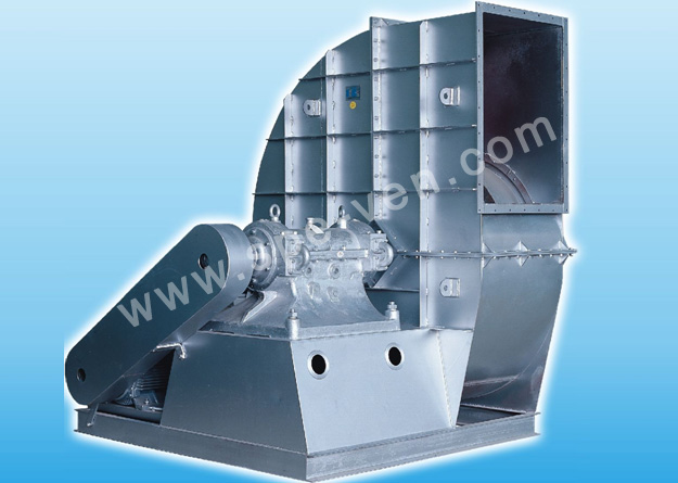
Centrifugal fan generally consists of parts of air hlet, impeller; scroll case, outlet, gearing device, base and motor.
effect of pressure extension.
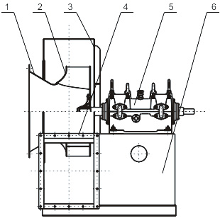
(1) inlet: inlet is made into an integer and set up at the side of scroll case of fan. Shaped conductor of axial cross section of inlet is streamli ne, the current can enter impeller equably so as to reduce flow loss and improve efficiency of impeller.
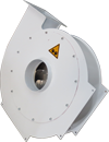
(2) Impeller: impeller is the most important part of centrifugal fan, its function is to invert mechanical energy into gaseous static pressure energy and kinetic energy. Impeller generally consists of front panel, blade, back panel and axial panel (wheel hub). Through balanceable emendation, operation will be smooth, and gas performance is good.
(3) Scroll case: scroll case is the passage of gas current, shaped conductor is usually log spiral with effect of current collection and guidance to outlet. Scroll case also has certain
(4) outlet: a passage for gas to flow out of fan. CXjtlet is drilled with bolt hole and can be connected with air pipe.
(5) Gearing device: consists of principal axis, bearhg housing, rolling bearing, pulley or clutch. One end of principal axis is connected with impeller, the other end is connected with piiley or clutch.
(6) Base: used to bear the weight of scroll case, beari ng device and motor, mantle and base are made into overall structure. It is not necessary for the user to make a nd in stall the base by himself, making installation easy.
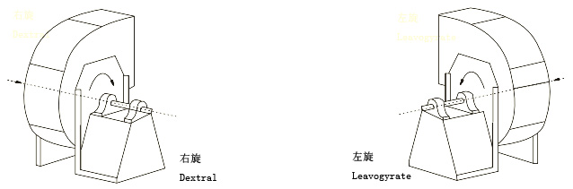
Centrifugal fan is divided into d extra I fan and laevogyra te fan according to rotary direction of impeller. It is called dextral fan and expressed with right if front view from one side of m oto r or gearing device finds impeller rotates clockwise, and called laevogyrate fan and expressed with left if front view from one side of motor or gearing device finds impeller rotates counterclockwise.
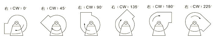
Location of outlet of centrifugal fan is expressed with the a ngle of outlet of mantle. The adjustment scope of location of outlet of centrifugal fan is generally 0 degree to 225 degrees and the space is 45 degrees. Information about angle of outlet will be provided upon goods ordering.
Common driving types of fan are as follows:
Driving Type A: centrifugal fan is not set up with gearing device,motor and impeller drive in connection.
Driving Type C: centrifugal fan is set up with gearing device, impeller and pulley are respectively located at both ends of gearing device, motor drives through pulley.
Driving Type D: centrifugal fan is set up with gearing device, impeller and clutch are respectively located at both ends of gearing device, motor drives through clutch.
(Remarks: Figuration of fan and its installation chart are shownon the table below.)
Parameters in blower performance table are worked out as follows:Ns4〜Ne6.3: on the basis that smoke medium status, namely air temperature t=20(TC, atmospheric pressurePa = 101325Pa, air density p =0.745 kg/m3, Those above : Na8〜 Ns 12.5worked out on the basis that smoke medium status, namely air temperature t=140°C, atmospheric pressure Pa = 101325Pa, air density p = 0.85 kg/m3 In case that the application status is not coincident with specific status in the performance table or blower's rotating speed changes, it is necessary to convert performance of application status into that of specific status in the performance table, and then select blower according to converted performance.
2. In selection of fan impact of , warp of total pressure value of fan itself is not considered. When the actual total pressure of fan is positive warp, volume flow will increase, and when the actual total pressure of fan is negative warp, volume flow will decrease.
Warp of volume flow of fan can be eliminated through the following methods:
hits:3639
hits:3745
hits:3880
hits:4020
hits:3759
hits:3833
hits:3787
hits:3730
hits:3814