Explosion Proof Fan>> back Warning: Missing argument 4 for GetPosStr(), called in /webHome/host5404692/www/En_proshow.php on line 88 and defined in /webHome/host5404692/www/include/func.class.php on line 396 HomeDraught fan seriesFan ProductsExplosion Proof Fandetailed
GB160 Explosion-proof fan
Pro Number:
Pro Spec:XK06-014-00685
Hits:4729
Pro Introduction:
Downloads:--
1 Overview
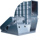
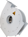
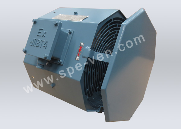
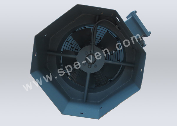
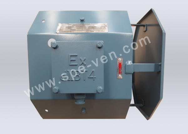
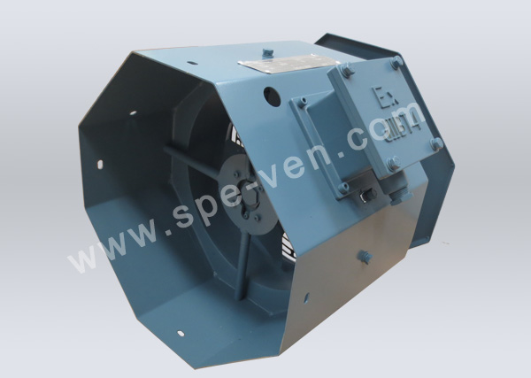
GB series flame-proof type axial flow fan is developed based on the original G series axial flow and is widely used in the forced air cooling of flame-proof type frequency control motor.
The anti-explosion performance of this series of fan conforms to the regulations of GB3836. 1-2010 Part one of explosive atmosphere: general requirements of equipments, GB3836. 2-2010 Part two of explosive atmosphere: equipments protected by the flame-proof enclosure “d”), the explosion-proof sign is Exd IIBT4 Gb. It’s applicable in the zone 1 and 2 of factories with IIA, IIB grade and the temperature groups are gas or explosive gas mixture formed by steam and air from T1-T4 groups.
The transmission media of fan is air or gas mixture formed by air and other non-corrosive gases with a maximum total pressure that would not exceed 1000Pa, the media inlet temperature should not exceed 40°C; the contents of dust and other solid impurities in the media should not exceed 100mg/m3,and there should be no cohesive and fibrous matters.
2 Meaning of models
3 Technical parameters
Please refer to table 1 and table 2 for the technical parameters of the fan
4 Operation conditions
The fan should be able to have rated operation in the following conditions 4.1Environmental conditions Altitude: the altitude should not exceed 1000m; Temperature: the operating ambient temperature is -20°C+40°C; Humidity: the highest relative humidity is 85% during the most humid month and the lowest temperature in this month should not exceed 25°C at the same time 4.2 Working power supply: the deviation between the working pressure and the rated value shown on the nameplate should not exceed ±5%. 4.3 The dust particles contained in the transmission medium should be less than 100mg/m3. 4.4 There is no violent vibration and impact
5 Key points of structure and anti-explosion
5.1 The fan is composed of three parts, main case, motor and fan blade, and the motor adopts the structure of outer rotor. 5.2 The parts which constitute the flame-proof enclosure include the end cap, rotor, junction box, seal ring, gland nut, and sufficient fixing bolts connected to the flame-proof enclosure, each bolt is installed with a spring washer to prevent it from loosening, otherwise, the anti-explosion performance would be lost. 5.3 The fitting surface between the flame-proof enclosures is the flame-proof adjoining plane, such as the plane and seam allowance adjoining plane between the end cap and rotor, the cylinder adjoining plane between the end cap and axis, the plane adjoining plane between the terminal box lid and base, the flame-proof adjoining plane should not be bumped or corroded. 5.4 The outside diameter lead-in cable of the fan’s junction box should conform to the inner diameter of seal ring at the inlet port. After the wiring, press seal ring with the gland nut, and make sure that there is no gap between the outside diameter of cable and inner diameter of seal ring, and between the outside diameter of seal ring and inner diameter of line outlet, thus the best anti-explosion performance could be realized. 5.5 The gap between the static parts such as fan blade and fan housing should not be smaller than 1/100 of the impeller’s maximum diameter and should not be smaller than 5mm. 5.6 The flame-proof adjoining plane is painted with No. 204-1 anti-rust oil. 5.7 Inner and outside grounding bolts are set inside the junction box and the fan enclosure, the ground connection should be reliable. 5.8 In rated conditions, the limiting value of stator winding’s temperature rise of the motor is 80K, and the maximum surface temperature of the enclosure (thermometer) should not exceed 130°C,the temperature of the cable inlet should not exceed 70°C. 5.9 The minimum outside diameter of cable that’s applicable to the connecting coil is "φ9、φ6.5"
6 Installation and maintenance
6.1 The mounting dimension of the fan is shown in the attached picture or according to the user requirements. 6.2 Check whether the contents on the nameplate are complete before the installation of the fan, whether there is anti-explosion qualification No. and whether the explosion-proof sign meets the field requirements. 6.3 Check whether the motor and enclosure of junction box have some crack or deformation that could influence the anti-explosion performance before the installation of fan. Check whether all the fastening bolts are tightened, the sparing washer should not be lost, whether the fan housing is deformed, and the fan blade should not bump or rub with other static parts. 6.4 Measure the stator winding of motor and insulation resistance among bases with 500V tramegger before the installation of fan, they should not be less than 1MQ, otherwise, they should be dried until the insulation resistance reaches the above mentioned requirements. Drying methods: blow with hot air, dry with incandescent lamp or infrared, short-circuit current could also be adopted; the current is 0.6 -0.8 times of the rated current. The motor that’s seriously influenced by dampness should not be dried with current so as to avoid electrolysis. No matter which method is adopted, the temperature of motor winding should be raised during the drying while the temperature should not exceed the limit regulated by insulation grade. 6.5 Refer to the key points of anti-explosion during the installation of fan 6.6 During the installation, install the fan on the rear end cover of the frequency control motor and fix it with bolts; according to the wiring diagram and rated power supply regulated by the nameplate, make the connection, and check the operation direction of the fan: rotate according to the direction of arrow on the enclosure. 6.7 During the running of the fan, there should not be any barrier that would block the air inflow within 50mm away from the protective screening of the air inlet, thus avoiding influencing the air inlet quantity. 6.8 There should not be any object entering the enclosure through the protective screening at the side of the air inlet during the running of the fan, thus avoiding damaging the impeller. 6.9 The fan should be inspected regularly and the dust and impurities inside should be cleaned regularly. 6.10 Make timely replacement when the seal ring is worn out. 6.11 It’s strictly forbidden to open the cover when the power is on. While opening the anti-explosion parts and installing them again, the flame-proof surface and fastening bolts should be painted with No. 204-1 anti-rust oil. 6.12 The fans should be stored in a dry environment with ventilation and no corrosive gas before they are installed.